Control Box
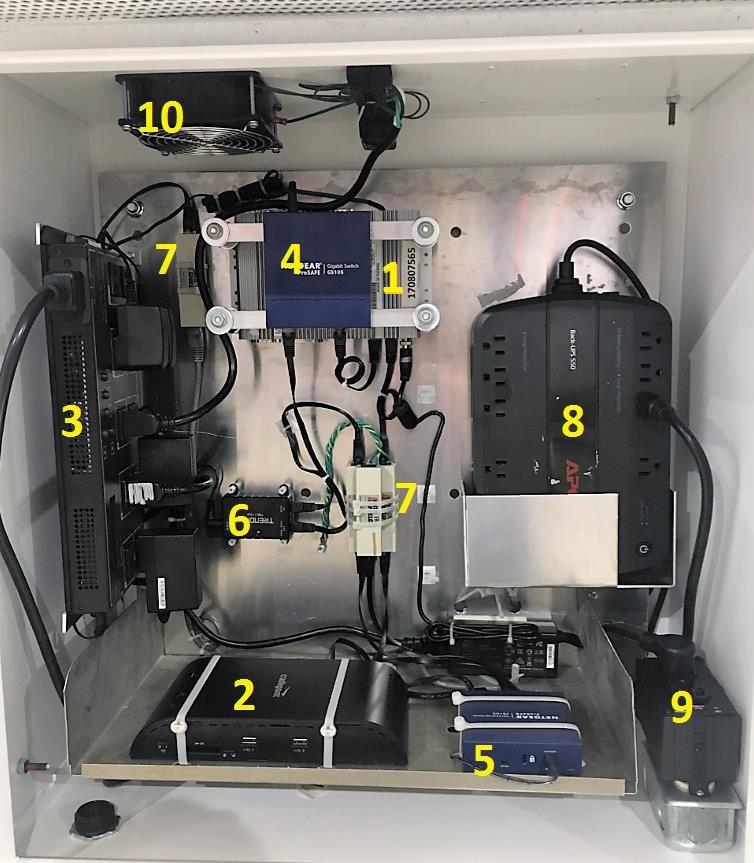
Components:
- PC: Control boxes can be built with a single PC, or with two PC’s. A control box with two PC’s is called a Primary-Secondary setup. The secondary is a backup. In control boxes with a backup PC, the primary PC is marked with gold and the secondary PC with silver. Their power supplies and power cables are marked the same way to make them easier to trace. Whenever replacing a PC, the power supply should also be changed. There are two Ethernet ports on each PC and they are not interchangeable. LAN 1 is the video port and LAN 2 is the communications port (this is standard for silver DFI PC’s but can vary on older PC’s). If the cables are reversed in the ports, the sign will not work, but it will not cause damage. Never power down a PC by removing the power plug from the back of the PC. Instead, unplug the AC connector for the power supply.
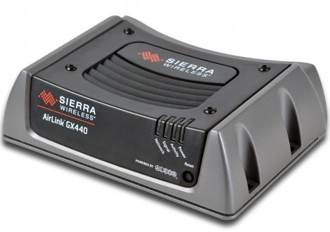
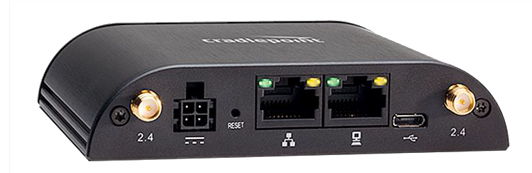
- Router: The router allows us to communicate with the display remotely, reports diagnostics, and retrieves data. The router is plugged into a communication switch via an Ethernet cable. While the router allows communication back and forth from the outside world, the switch acts as a hub and allows communication between the router and the devices inside the control box. When utilizing an operator supplied router, the operator is responsible for communication based maintenance. This includes power cycling, SIM card reseating, SIM card replacement, and device replacement.
- WPS/CPS: The Web Power Switch (black) or CPS100 (blue) is mounted on the left and is plugged into a “Battery Backup + Surge Protection” outlet on the UPS. The Web Power Switch is an intelligent power strip that monitors internet access and allows us to remotely restart devices plugged into it. It is important to keep power supplies plugged into their original outlets on the Web Power Switch. Switching the outlet a device is plugged into without informing the Formetco Help Desk could result in loss of functionality.
- Video Switch: This is a 5 port Gigabit unmanaged switch. The video switch is simply an expansion of the video port on the PC. Imagine it as a multi outlet extension cord. There is a short Ethernet cable ran between LAN1 of the PC and the video switch. Data is carried to the display from the video switch by longer Ethernet cables. Because this switch is unmanaged, video connections can be made in any port of the switch.
- Communication Switch: This is a 5 port Gigabit unmanaged switch. The communication switch (sometimes shortened to comms switch) is simply an expansion of the video port on the PC. Imagine it as a multi outlet extension cord. There is a short Ethernet cable ran between LAN2 of the PC that first goes into an Ethernet surge suppressor and then into the communication switch. The switch is a hub that allows the PC to communicate with the backup PC (if installed), router, POE, and web power switch/CPS.
- Power Over Ethernet: The power over ethernet (POE) connects the camera to the communications switch. The cable that enters the control box from the camera plugs into the Power + Data ethernet port on the POE. The Data In port is connected to the communications switch.
- Ethernet Surge Suppressor: A sacrificial in-line ethernet surge suppressor. Not critical to operation and can be bypassed by a single ethernet cable. Used to protect the more valuable components in the control box.
- UPS (Uninterruptable Power Supply): Backup battery that temporarily keeps the control box on stable power during power outages and fluctuations. The green light near the power button should always be on. In case of failure, the UPS can be bypassed by plugging the WPS or CPS100 directly into the outlet in the bottom right.
- Isoblok Surge Suppressor: Provides surge protection on the power coming into the control box. The “Protection Present” and “Line Ok” lights should be green at all times. The red “Fault” light should never be on. If the red indicator light is on, there is likely a bad ground or the polarity is reversed. This part can be bypassed if it fails by removing it and plugging the UPS power cable directly into the duplex outlet underneath. Any trained technician can change this part because it plugs directly into the outlet. An electrician is recommended to troubleshoot if there is a wiring issue.
- Thermostat & Fan: There is an exhaust fan in the top of the cabinet. It will not always be running because it is connected to a thermostat that is set to 95°F.